 |
| |||||
| ||||||||||||

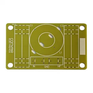
Crossover PCB designed for a range of high pass filters.
This PCB provides a tidy solution for manufacturing 2nd or 3rd order high pass filters from 1200Hz upwards.
Dimensions 91 x 56mm.
For second order filters, Place the capcaitor at C1 and the inductor in the middle position indicated with a circle (L1). The inductor position is predrilled to allow use of cable ties for securing the inductor. When using in 2nd order configuration, a link wire should be solder across the terminals of the right hand rectangle (C2) to complete the circuit to the output. For third order filters, C2 provides a position for an additional capacitor.
You can read more about passive crossovers here: http://www.speakerwizard.co.uk/category/speaker-systems/crossovers/
Need some help calculating values? Why not try our crossover calculator: Crossover Calculator
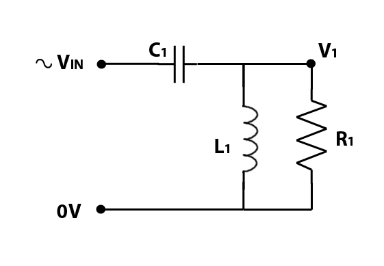
Circuit diagram for 2nd order high pass filter: R1 represents the loudspeaker. C1 is made using position C1 on the PCB
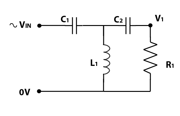
Circuit diagram for 3rd order high pass filter: R1 represents the loudspeaker. C1 is made using position C1 on the PCB, C2 is made using position C2 on the PCB
Detailed specifications unavailable, please EMAIL the sales office for additional information.
| Other Convair Electronics products similar to Convair Electronics PCB9002 mk2 For High-Pass Filter: |
|
If you find 'Convair Electronics PCB9002 mk2 For High-Pass Filter' at a lower price from an authorised UK dealer, tell us and we'll aim to match it. Request a price match. Terms & Conditions.